

48V hub motor wiring diagram is essential for smooth and reliable assembly and maintenance of electric hub motor. QS motors feature standardized wiring for great clarity and broad compatibility, pairing perfectly with most controllers.
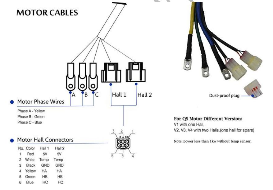
1. Motor Phase Wires (Power Delivery)
These three thick, color-coded wires carry the main power from the controller to the motor, driving the rotor:
Phase A: Yellow
Phase B: Green
Phase C: Blue
2. Hall Sensor Connectors (Position Feedback)
The Hall sensor harness provides real-time rotor position data to the controller, ensuring smooth, efficient operation at all speeds. Our motors use a standardized 6-pin connector with the following pinout:
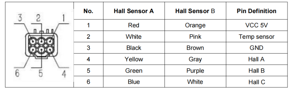
QS motors offer different Hall configurations to suit your needs:
V1: Single Hall sensor setup
V2/V3/V4: Dual Hall sensors (one as a spare for enhanced reliability)
Note: Motors under 1kW do not include a temperature sensor, simplifying the harness.
3. Additional Features
Dust-proof plug: Included for unused Hall connectors, protecting against moisture and debris in rugged conditions.
Modular design: The separate phase and Hall connectors make installation, maintenance, and troubleshooting straightforward.
Why This Wiring Design Works for You
Universal Compatibility: Standard color coding and pinouts match most 48V e-bike controllers, reducing guesswork during setup.
Future-Proof Flexibility: Dual Hall options and temperature sensing support high-performance builds, while the basic V1 setup works for casual riders.
Durability: Weather-resistant connectors and optional dust-proofing ensure long-term reliability in all riding environments.
Whether you’re building a custom e-bike or replacing a motor, our clear 48V hub motor wiring diagram takes the stress out of installation. Pair it with a compatible controller, and you’ll be ready to hit the road in no time!
